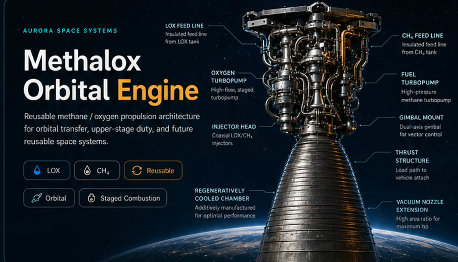
Aurora Space Systems
Methalox Orbital Engine
Reusable methane / oxygen propulsion architecture for orbital transfer, upper-stage duty, and future reusable space systems.
Public-safe technical posture
- No proprietary Blue Origin data or logos.
- No fake certified performance claims.
- Architecture-level subsystem credibility.
- Graphics use the approved rendering direction.
Public Architecture Brief
One engine page. Fourteen real assembly conversations.
This folder presents the Methalox Orbital Engine as a public, conceptual architecture. It highlights major assemblies and subsystem interfaces using credible, high-level data to support technical understanding and informed discussion.
Detailed private CAD, performance margins, proprietary materials, internal verification data, actual injector geometry, turbopump sizing, and control timings remain offline. The goal is to show disciplined systems thinking, not claim a flight-certified engine.
What engineers should see
- Feed, pump, injector, chamber, cooling, nozzle, controls, structures, manufacturing, testing, and reuse are treated as one system.
- The page avoids magic numbers and unsupported claims.
- Each card opens to a module page with public-safe technical text.
Engine Assembly Cards
Subsystem map
Graphics are pulled from the approved methalox render direction and reused as section thumbnails, with Card 1 using the larger technical callout rendering as requested.
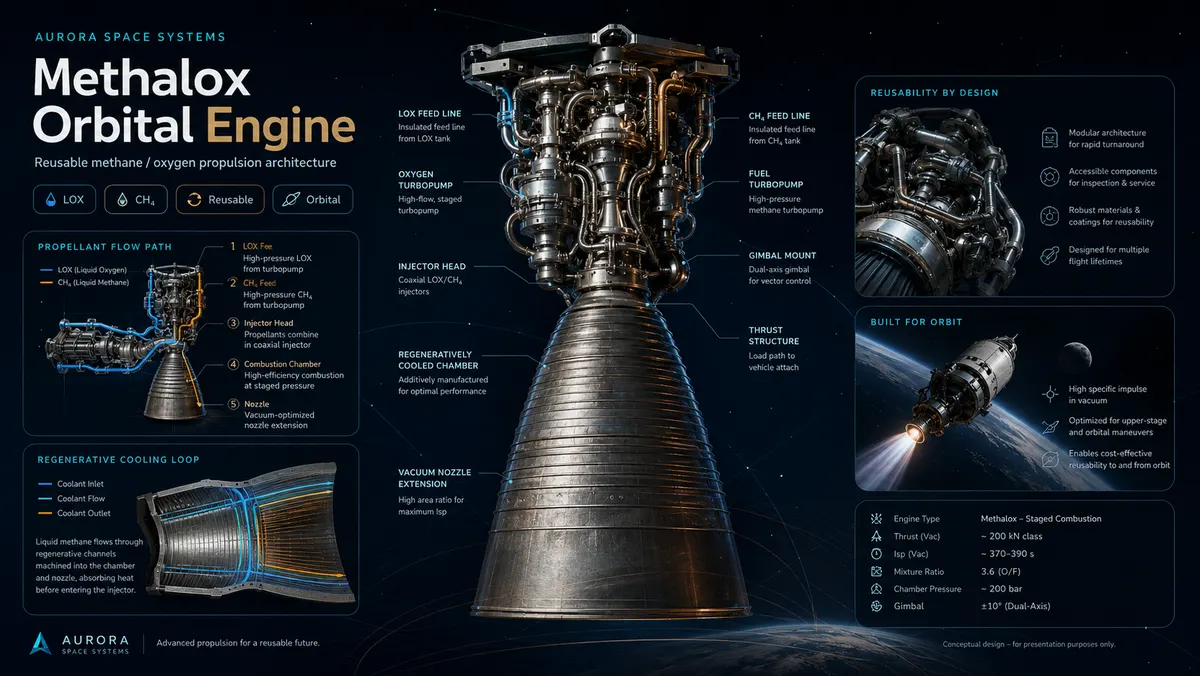
1. System Overview
Architecture-level overview of the Methalox Orbital Engine, its public vocabulary, major assemblies, and reusable upper-stage design intent.
Open Section →
2. Propellant Feed Architecture
LOX and methane routing, isolation, conditioning, purge, pressure regulation, and engine-interface logic.
Open Section →
3. LOX Turbopump Assembly
Oxygen turbopump assembly vocabulary: inducer, impeller, bearings, seals, turbine drive, instrumentation, and thermal boundaries.
Open Section →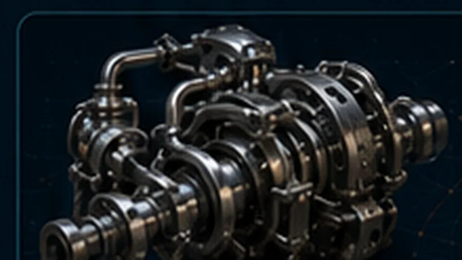
4. Methane Turbopump Assembly
Fuel turbopump assembly with methane-side thermal conditioning, seal strategy, drive integration, and control interfaces.
Open Section →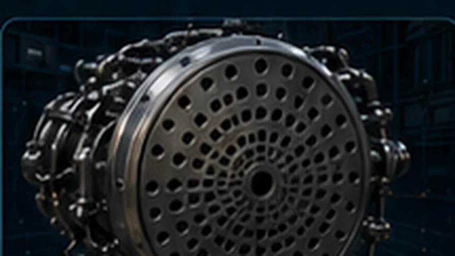
5. Injector Head & Mixer
Public-facing injector vocabulary: element pattern, mixing logic, face cooling, stability, and manufacturability without exposing geometry.
Open Section →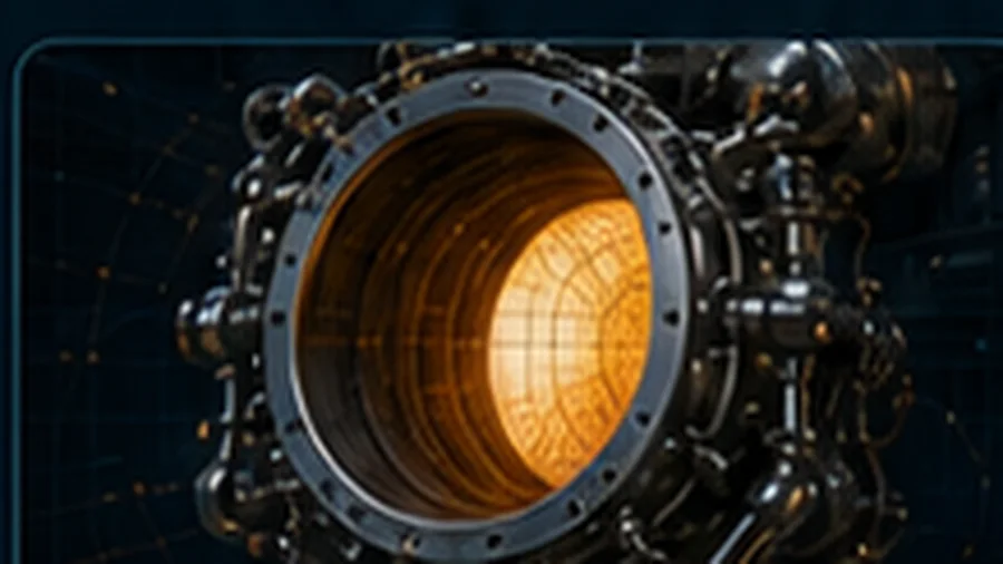
6. Combustion Chamber
Chamber geometry, heat load path, start transient behavior, wall cooling, and durability framing.
Open Section →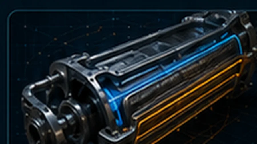
7. Regenerative Cooling Network
Cooling-channel routing, methane heat pickup, manifold strategy, throat-zone thermal margins, and inspection considerations.
Open Section →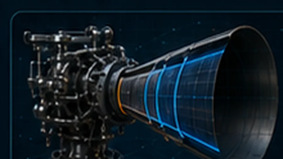
8. Nozzle & Vacuum Extension
Nozzle contour, expansion ratio trade space, extension packaging, thermal gradients, and vacuum operation framing.
Open Section →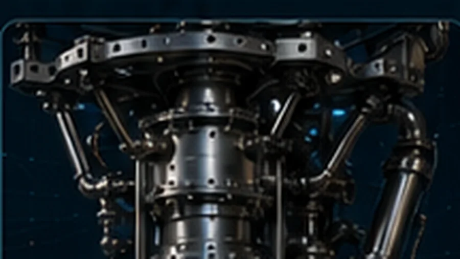
9. Gimbal Mount & Actuation
Thrust-vector-control framing: gimbal ring, actuators, spherical bearing logic, load paths, and vehicle interfaces.
Open Section →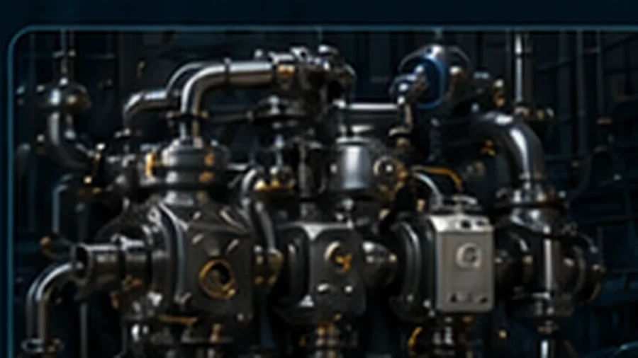
10. Valves, Sensors & Controls
Valve actuation, instrumentation, closed-loop control, ignition sequencing, abort logic, and health monitoring framing.
Open Section →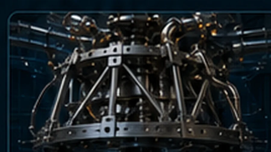
11. Structural Frame / Thrust Structure
Load path from engine to vehicle, mounting frame, thrust structure, thermal isolation, access clearances, and integration.
Open Section →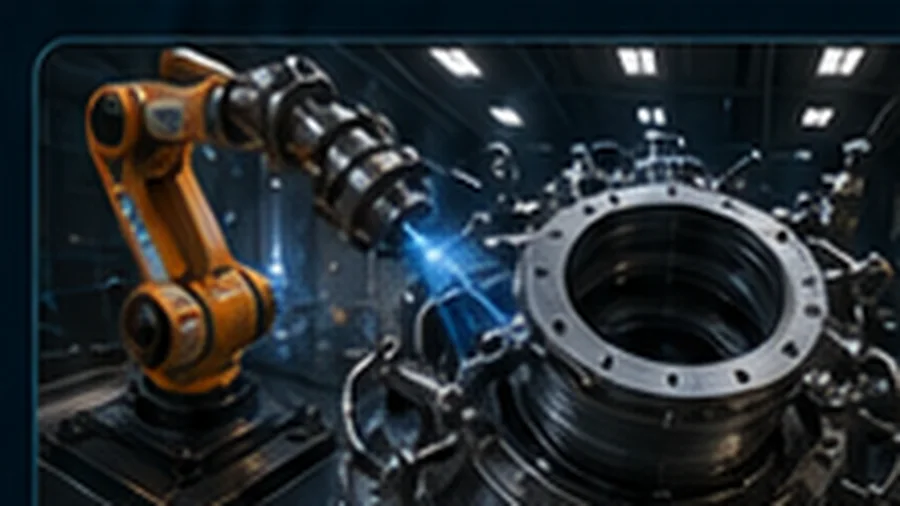
12. Manufacturing & Inspection
Fabrication strategy, additive manufacturing potential, weld / braze / join inspection, metrology, and QA flow.
Open Section →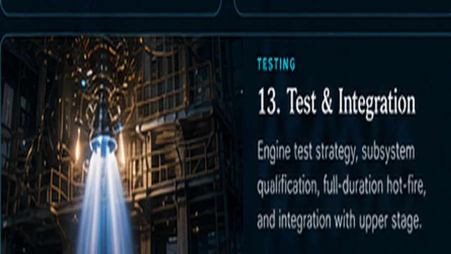
13. Test & Integration
Subsystem qualification, cold-flow, chilldown, ignition tests, hot-fire progression, data review, and vehicle integration.
Open Section →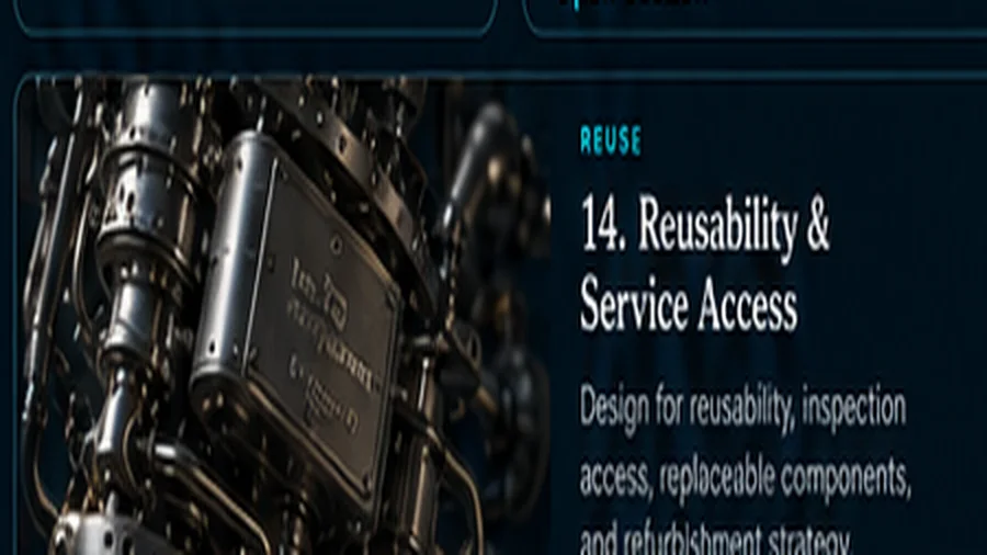
14. Reusability & Service Access
Maintenance access, inspection zones, replaceable modules, turnaround doctrine, corrosion/contamination controls, and lifecycle thinking.
Open Section →All data is subject to change. Detailed private design data, verification results, margins, CAD, and proprietary engineering remain offline.