← Back to Methalox Orbital Engine

Structures · Module 11

Structural Frame / Thrust Structure

Load path from engine to vehicle, mounting frame, thrust structure, thermal isolation, access clearances, and integration.

Public-safeAssembly-levelNo proprietary dataInterview-ready vocabulary
Structural Frame / Thrust Structure technical rendering

Architecture Role

The thrust structure is the physical contract between engine and vehicle. A credible page needs to show the load path, mounting logic, thermal separation, routing clearance, sensor/valve access, and compatibility with the upper stage or orbital vehicle.

This page should be especially strong for mechanical design discussion. It can show structural vocabulary and integration thought while keeping actual FEA, fastener details, material allowables, and interface drawings out of the public layer.

Public boundary: this page intentionally avoids private CAD, dimensions, line sizing, materials trade data, performance margins, control logic, injector geometry, pump maps, and verification results.

Subsystem Focus

Focus 1Show how thrust load gets from chamber/nozzle into the vehicle.
Focus 2Discuss structural frames, gimbal loads, thermal isolation, vibration, and service clearance.
Focus 3Avoid detailed FEA, load cases, material allowables, and fastener specifications.
Focus 4Treat the thrust structure as both mechanical architecture and maintenance packaging.

Professional Discussion Frame

For a technical audience, the strongest posture is to discuss interfaces, requirements flow-down, failure modes, manufacturability, inspection access, and verification strategy. That keeps the conversation grounded and prevents the page from sounding like unsupported propulsion claims.
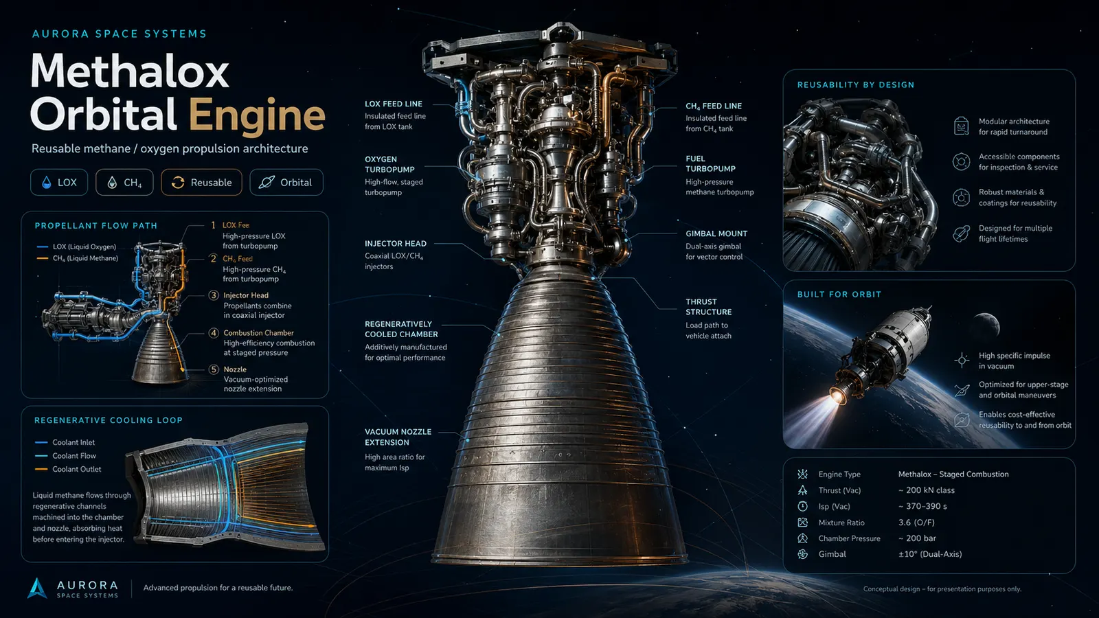
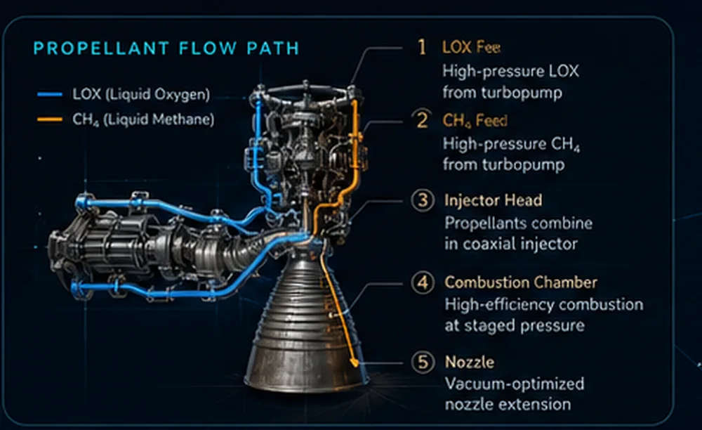
System overview boardFeed system diagramRegenerative cooling loop
i
Concept layer only.
Use this as a public-facing architecture explanation, not as certified engine design data.