← Back to Methalox Orbital Engine

Combustion · Module 6

Combustion Chamber

Chamber geometry, heat load path, start transient behavior, wall cooling, and durability framing.

Public-safeAssembly-levelNo proprietary dataInterview-ready vocabulary
Combustion Chamber technical rendering

Architecture Role

The combustion chamber page should communicate coupled engineering. Chamber geometry is not a single profile; it is a negotiation between combustion efficiency, thermal margin, pressure loading, wall cooling, throat durability, manufacturing repeatability, and inspection after test or flight.

The public architecture can discuss the chamber as the engine's high-energy core and explain why regenerative cooling, material compatibility, hot-gas wall durability, and transient start/stop conditions are important. It should not claim verified chamber pressure or publish internal geometry without test-backed justification.

Public boundary: this page intentionally avoids private CAD, dimensions, line sizing, materials trade data, performance margins, control logic, injector geometry, pump maps, and verification results.

Subsystem Focus

Focus 1Treat chamber design as coupled combustion, thermal, structural, and manufacturing architecture.
Focus 2Explain heat flux, wall temperature, throat region sensitivity, and transient loads in plain technical language.
Focus 3Keep internal dimensions and performance values out of the public-facing page.
Focus 4Connect chamber durability to hot-fire testing and post-test inspection.

Professional Discussion Frame

For a technical audience, the strongest posture is to discuss interfaces, requirements flow-down, failure modes, manufacturability, inspection access, and verification strategy. That keeps the conversation grounded and prevents the page from sounding like unsupported propulsion claims.
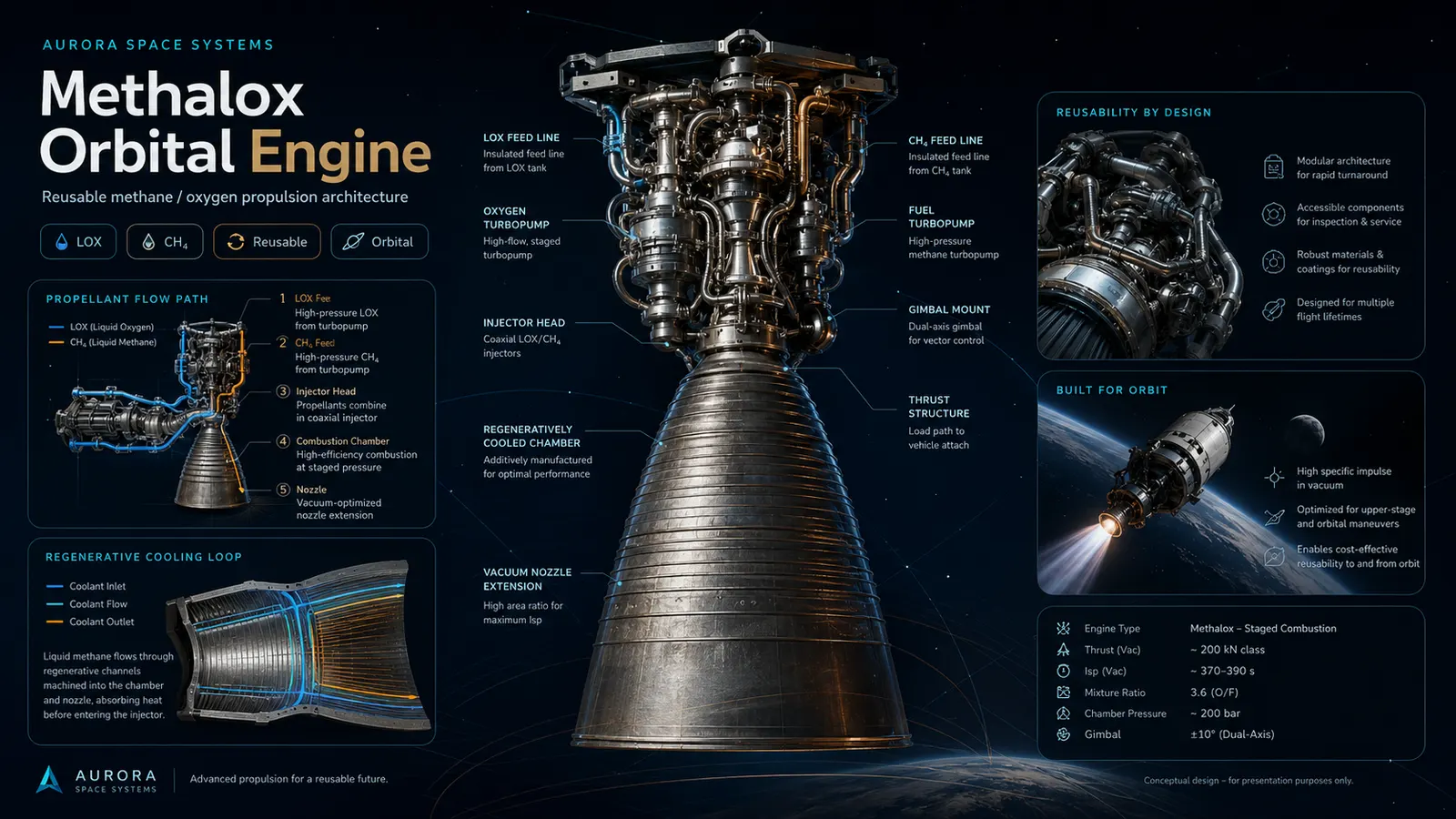
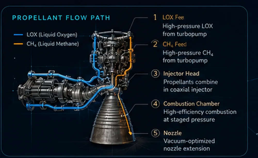
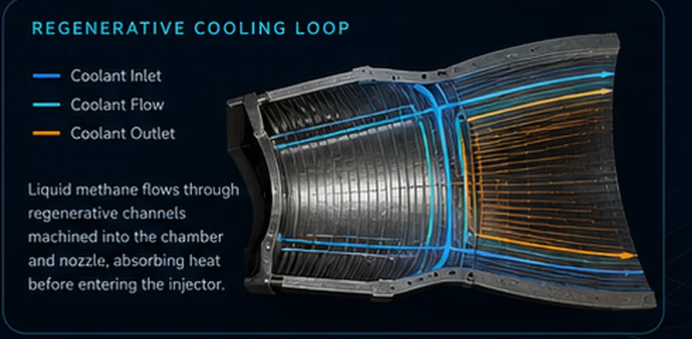
System overview boardFeed system diagramRegenerative cooling loop
i
Concept layer only.
Use this as a public-facing architecture explanation, not as certified engine design data.