
Houses the core, control rods, internal structures, and pressurized primary coolant that carries fission heat out of the vessel.
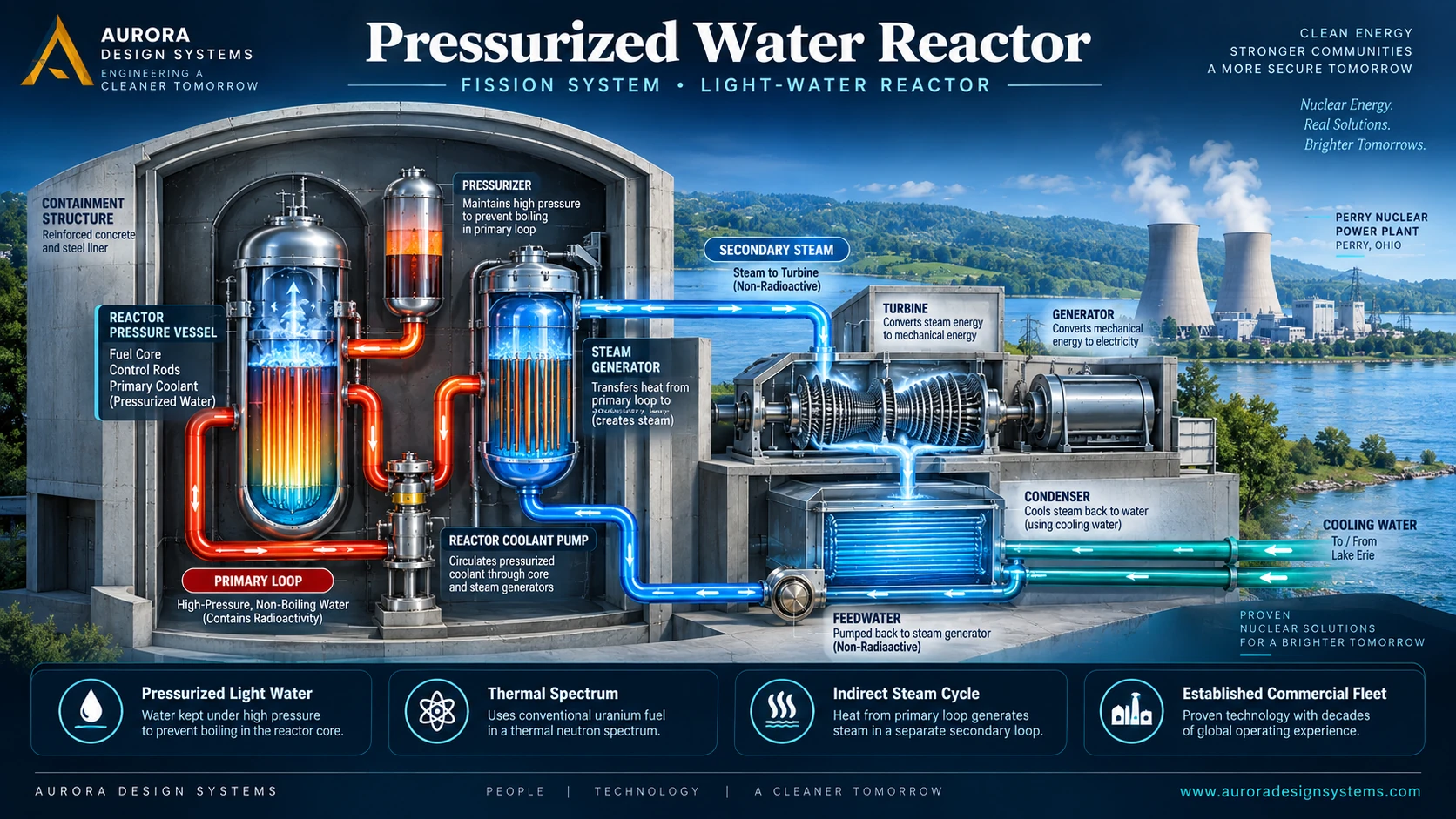
Fission System • Light-Water Reactor
Pressurized Water Reactor
A pressurized water reactor (PWR) keeps the radioactive primary coolant under high pressure so bulk boiling does not occur in the core. Heat is transferred through steam generators to a separate secondary loop, where steam is produced for the turbine-generator.
Pressurized Light WaterThermal SpectrumSeparate Secondary LoopEstablished Commercial Fleet
Why the architecture matters: separating the reactor coolant system from the turbine steam system is the defining PWR feature. The primary loop carries reactor heat; the secondary loop converts that heat to steam; a third cooling-water path rejects unused heat at the condenser.
Phase 4 • Page-Specific Technical Summary
What this reactor category means
System definition
A thermal-spectrum light-water reactor with a pressurized radioactive primary circuit and a physically separate steam-producing secondary circuit.
A thermal-spectrum light-water reactor with a pressurized radioactive primary circuit and a physically separate steam-producing secondary circuit.
Intended applications
Large-scale firm electricity, life-extension and replacement studies, integral-SMR derivatives, and selected cogeneration concepts where design and licensing permit.
Large-scale firm electricity, life-extension and replacement studies, integral-SMR derivatives, and selected cogeneration concepts where design and licensing permit.
Why it matters
PWRs form the largest reactor family in the U.S. commercial fleet and one of the most widely deployed nuclear architectures worldwide.
PWRs form the largest reactor family in the U.S. commercial fleet and one of the most widely deployed nuclear architectures worldwide.
Public boundary
Technology classification, component relationships, maturity, engineering challenges, and public licensing context only. No design calculations, operating procedures, control logic, or procurement data.
Technology classification, component relationships, maturity, engineering challenges, and public licensing context only. No design calculations, operating procedures, control logic, or procurement data.
Expanded Visual References
PWR systems and technical overview
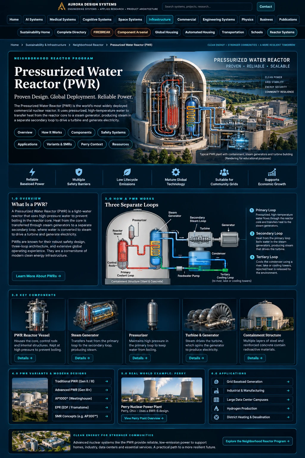
The supplied PWR graphics are retained as supporting references: one vertical systems page and one broad system explanation graphic.
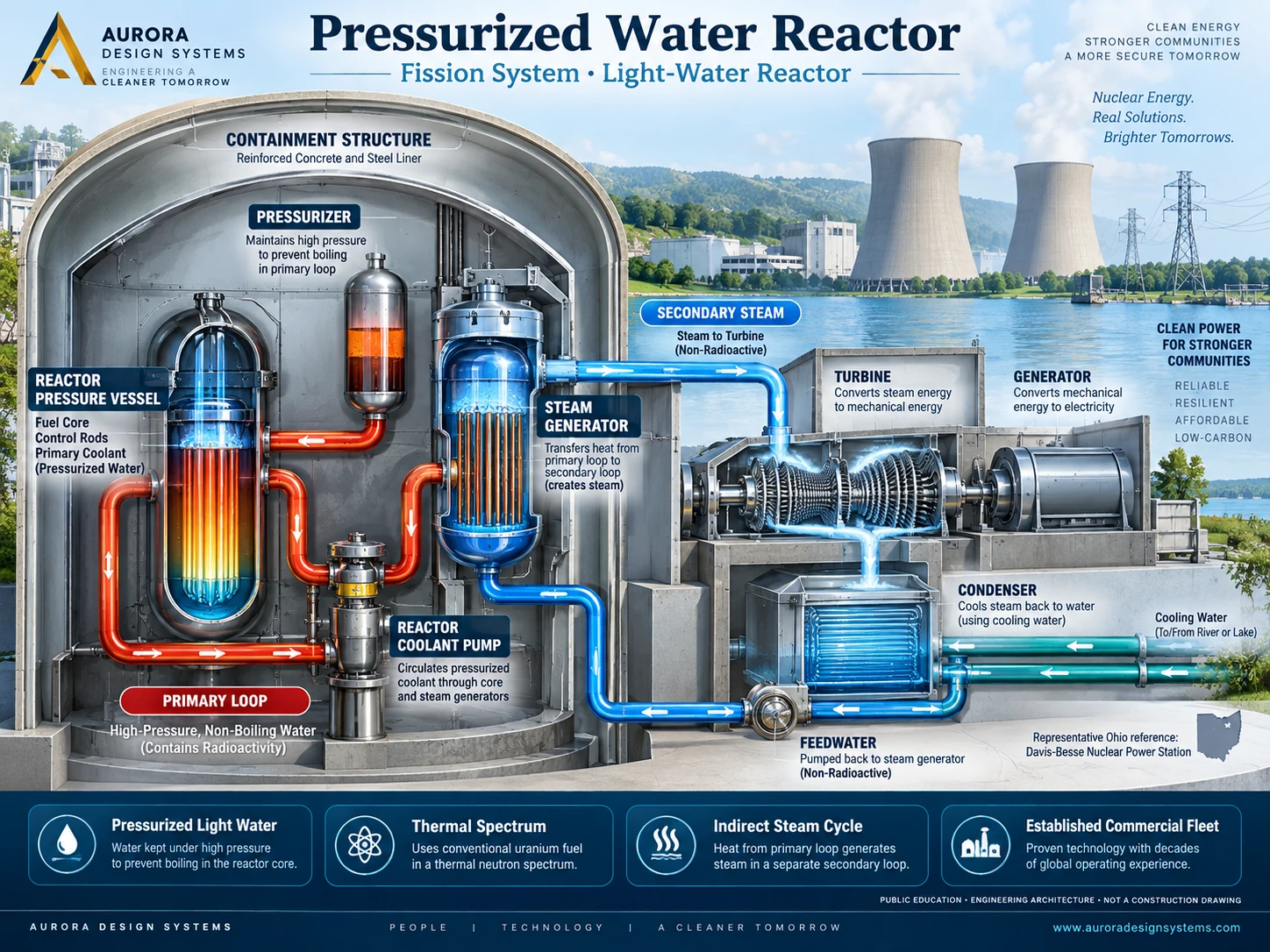
System Architecture • Public-Level Component Map
Major components and their roles
Provides pressure control and surge volume for the primary coolant system so the reactor coolant remains liquid during normal operation.
Transfers heat across tube walls from the radioactive primary coolant to a separate secondary-water inventory that becomes steam.
Circulate primary coolant between the reactor vessel and steam generators in conventional pumped-loop PWR arrangements.
Encloses the reactor coolant system and major nuclear steam-supply components within a robust pressure and radiological barrier.
Uses secondary-loop steam to convert thermal energy to mechanical rotation and then electrical power.
Condenses turbine exhaust steam back to water using an external heat sink, completing the secondary power cycle.
Returns conditioned secondary water to the steam generators so the power-conversion loop can continue.
System Logic
How a PWR works — three distinct thermal paths
Fission heats the primary loop
The reactor core transfers heat to pressurized primary water while the pressurizer maintains a system condition that prevents bulk boiling in the core.
Primary coolant reaches the steam generator
Hot reactor coolant flows through steam-generator tubing. The two water inventories remain physically separated by the heat-transfer boundary.
Secondary water becomes steam
Heat transferred through the steam-generator tubes boils secondary water, producing steam for the turbine without sending primary coolant into the turbine hall.
The turbine produces electricity
Secondary steam expands through the turbine, which drives the generator. Exhaust steam then enters the condenser.
Heat is rejected and feedwater returns
An external cooling-water system removes condenser heat, while pumps return condensed secondary water to the steam generators.
Phase 4 • Technical Education + Terminology + Accuracy
Learn the System
This learning layer explains the system in public engineering language. Definitions are intentionally conceptual: they teach terminology and relationships without providing operating procedures, design set-points, construction dimensions, or protected implementation details.
Maturity checkpoint: Established commercial reactor family with the largest share of the operating U.S. power-reactor fleet.
System walkthrough
How it works — at a safe public level
- Fission heats pressurized water in the reactor core.
- The pressurizer keeps the primary coolant at high pressure so bulk boiling does not occur in the core.
- Primary coolant transfers heat through steam generators to a separate secondary water system.
- Secondary steam drives the turbine-generator.
- A condenser and external cooling system reject remaining heat and return water to the steam generators.
Key distinction: The defining PWR feature is separation between the radioactive primary coolant system and the turbine steam system.
Technical vocabulary
Terms worth knowing
Pressurizer
A PWR component that controls primary-system pressure so bulk boiling does not occur in the reactor core.
Indirect steam cycle
A power cycle in which reactor heat is transferred across a heat exchanger to a separate steam system before reaching the turbine.
Steam generator
A heat exchanger that uses reactor-system heat to produce steam in a separate water circuit.
Reactor coolant pump
A pump that circulates primary coolant through the reactor core and connected heat exchangers in designs that use forced circulation.
Primary loop
The heat-transport circuit that directly removes heat from the reactor core.
Secondary loop
A separate heat-transport or steam circuit that receives heat through a heat exchanger without directly circulating through the core.
Tertiary cooling loop
The external heat-rejection circuit associated with a condenser or heat sink, often using water or air.
Fuel assembly
An engineered grouping of nuclear fuel elements arranged to support cooling, structural integrity, neutron control, and refueling.
Containment
A robust physical barrier surrounding key reactor systems to limit release of radioactive material during abnormal events.
Condenser
A heat exchanger that turns turbine exhaust steam back into liquid water so the working fluid can be reused.
MWe
Megawatts electric: the electrical power output delivered by a generating system.
MWth
Megawatts thermal: the rate of heat production before conversion to electricity or useful process heat.
Authoritative learning referencesU.S. NRC — Pressurized Water Reactors ↗
Why the Separate Loop Matters
Primary and secondary systems are intentionally different
The primary circuit is part of the reactor coolant pressure boundary and carries heat directly from the core. The secondary circuit receives that heat through steam-generator tubes and sends steam to the turbine-generator. Under normal plant conditions, the two water inventories do not mix. This arrangement concentrates most routine radioactive-water control inside the nuclear steam-supply side of the plant while allowing a conventional steam turbine cycle on the secondary side.
That separation also creates important engineering responsibilities: steam-generator tube integrity, high-pressure primary boundary management, chemistry control, pump reliability, pressurizer behavior, and inspection of large components throughout long plant lifetimes.
Public takeaway
PWR ≠ “BWR with a pressurizer.” The entire heat-transfer and turbine interface is different. The BWR boils reactor coolant in-vessel and sends that steam directly to the turbine; the PWR maintains a liquid primary loop and creates turbine steam in separate steam generators.
PWR ≠ “BWR with a pressurizer.” The entire heat-transfer and turbine interface is different. The BWR boils reactor coolant in-vessel and sends that steam directly to the turbine; the PWR maintains a liquid primary loop and creates turbine steam in separate steam generators.
Family Comparison
PWR versus BWR at a glance
| Feature | Pressurized Water Reactor | Boiling Water Reactor |
|---|---|---|
| Core coolant | Light water kept under high pressure to prevent bulk boiling. | Light water intentionally boils in the reactor vessel. |
| Steam production | Steam generated in a separate secondary loop through steam generators. | Steam generated directly in the reactor vessel. |
| Turbine steam boundary | Secondary-loop steam is physically separated from primary reactor coolant during normal operation. | Reactor-generated steam is routed directly to the turbine. |
| Signature components | Pressurizer, steam generators, primary coolant pumps. | Steam separators/dryers, recirculation system, direct main-steam path. |
| Commercial maturity | Established large global fleet with multiple vendor lineages. | Established global fleet with multiple generations and newer modular descendants. |
Application Context
Where the family fits
Utility generation
Firm grid electricity from mature large commercial units with extensive operating, maintenance, and regulatory experience.
Existing-site modernization
Life extension, major-component replacement, digital modernization, uprates, and site-specific plant improvement programs.
Advanced large PWRs
Generation III/III+ designs such as AP1000- and EPR-class plants preserve the PWR cycle while changing safety architecture, construction strategy, and plant integration.
Integral PWR SMRs
Some small modular reactors move major primary-system components into a more integrated vessel arrangement while retaining PWR thermodynamic principles.
Design Lineage
PWR family evolution
Fleet foundation
Large loop-type PWRs established the modern commercial architecture across the United States, Europe, Asia, and other nuclear markets.
Generation III / III+
Newer large plants emphasize improved safety systems, standardization, digital controls, long design life, and updated construction approaches.
AP1000-class evolution
Passive-safety large PWRs use the same primary/secondary cycle while reducing dependence on some active safety functions during defined accident conditions.
Compact modular branch
Integral designs place more of the primary system inside a compact nuclear steam-supply module, creating a separate licensing and deployment path rather than a scaled copy of a large PWR.
Representative Ohio Reference
Davis-Besse Nuclear Power Station
Davis-Besse in Oak Harbor, Ohio is a useful regional example of a commercial PWR. The NRC identifies Unit 1 as a Babcock & Wilcox raised-loop pressurized water reactor with a dry ambient-pressure containment. The current NRC facility record lists Vistra Operations Company LLC as operator and a renewed operating-license expiration date of April 22, 2037.
Pressurized Water Reactor (PWR)
Babcock & Wilcox raised-loop PWR
Oak Harbor, Ohio, near the western Lake Erie region
A regional reference plant for explaining PWR architecture—not a template for a new Aurora reactor project.
Why this reference is useful
It gives Ohio readers a real commercial PWR example distinct from Perry’s BWR architecture. That comparison makes the two light-water families easier to understand without reducing either one to a generic “nuclear plant.”
Important: plant-specific dimensions, safety analyses, operating limits, procedures, and security details are outside this public page.
Infrastructure Integration
Firm power for industrial and future compute campuses
Large PWRs produce steady, high-capacity electrical output, which is why nuclear generation increasingly enters discussions about industrial electrification, hydrogen production, grid reliability, and high-density computing. The reactor is only one part of that equation. Transmission availability, cooling-water access, maintenance outages, backup power, grid interconnection, load-following requirements, financing, siting, and licensing determine whether nuclear generation is appropriate for any specific campus.
Future photonic, DNA/molecular, neuromorphic, cryogenic, or hybrid data centers may substantially change the shape of computing loads and cooling systems. The power architecture should therefore be treated as an evolving infrastructure interface rather than assuming today’s GPU-campus profile forever.
10-Phase Reactor Program • Phase 2
Standardized fission technical specification
Standardized public-safe fields support comparison across every fission and fusion family. Values are intentionally qualitative; licensing data, dimensions, operating windows, calculations, control logic, and build instructions remain offline.
Light water under pressure in the primary system; separate secondary steam system
Thermal spectrum
Low-enriched uranium ceramic fuel in design-specific assemblies
Large commercial plants dominate the established fleet; advanced integral and modular derivatives are separate designs
Indirect steam Rankine cycle through steam generators
Established commercial fleet with newer advanced and modular branches at design-specific maturity levels
Spent fuel remains high-level radioactive material requiring cooling, storage, and long-term disposition. Reprocessing does not remove all waste obligations.
Specification boundary: Family-level technology classification and lifecycle context—not a vendor datasheet, safety analysis, procurement specification, or construction package.
Ten-Phase Reactor Program · Phase 5
Safety, licensing, lifecycle & public trust
Phase 5 treats safety as a full lifecycle obligation: site and license basis, fuel/material supply, operation, environmental controls, safeguards, emergency preparedness, waste, decommissioning, and disciplined public claims.
Reactivity control, high-pressure primary-boundary integrity, steam-generator integrity, cooling and decay-heat removal, containment, severe-accident mitigation, station power, aging management, and spent-fuel interfaces.
For U.S. commercial power, Parts 50 and 52 remain established licensing routes. Part 53 is also available as a risk-informed, performance-based, technology-inclusive alternative for eligible class 103 commercial plants. The actual route is design- and application-specific.
Evaluate cooling-water source and heat rejection, withdrawal and consumption, thermal discharge, aquatic impacts, steam-generator and chemistry programs, construction footprint, transmission, and site-specific environmental permits. A separate secondary loop does not eliminate external heat rejection.
Conventional light-water fleets typically use low-enriched uranium fuel. Fuel procurement, fabrication, transport, outage handling, pool or dry storage, and long-term disposition are part of the plant lifecycle; fuel availability is not a substitute for licensing or safety findings.
Plan for operational radioactive waste, activated components, spent nuclear fuel, outage waste, and eventual decommissioning. Decommissioning funding, dismantlement, waste packaging, site release, and long-term spent-fuel disposition remain lifecycle obligations.
Apply graded material control and accounting, physical protection, cybersecurity, transport controls, insider-risk controls, and international safeguards as applicable to the material, facility, mission, and jurisdiction. Public pages must not reproduce Safeguards Information, sensitive security layouts, response tactics, or adversary-useful detail.
Large commercial light-water reactors use the established emergency-preparedness framework, including 10 CFR 50.47 and Appendix E as applicable. Emergency plans, zones, drills, offsite coordination, and protective actions are regulator- and site-specific.
State the maturity actually achieved, name the applicable authority, separate family-level evidence from project approval, and distinguish demonstrated performance from projections or marketing.
May describe the family as commercially established and supported by extensive operating and regulatory experience. Maturity of a family does not automatically establish the safety, cost, schedule, or licensing outcome of a specific plant.
Do not claim inherently safe, meltdown-proof, zero-waste, zero-impact, proliferation-proof, unguarded, maintenance-free, zero-emergency-planning, or automatically cheaper. Do not imply that one plant's license or operating record transfers to another design or site.
Phase 5 evidence:NRC — Power Reactor Licensing ↗NRC — Emergency Preparedness ↗NRC — Nuclear Security & Safeguards ↗NRC — New Reactor Environmental Review ↗
Public classification only: This is not a safety finding, licensing opinion, environmental permit, emergency plan, security plan, safeguards determination, waste-acceptance decision, or legal advice. Exact obligations belong to the applicable regulator and project authority.
Public Technical References
Authoritative starting points
These links support public education and page maintenance. They do not replace plant-specific licensing documents.
Phase 7 • Release Certification & Production Integration
Release certification
This page has passed the Reactor Programs Phase 7 branch-level release review for internal routing, asset references, canonical metadata, maturity and terminology controls, source-authority links, accessibility essentials, responsive markup, and release traceability.
Production boundary: this certification covers the Reactor Programs branch package. Parent-site shared CSS, navigation, search, logo, and global assets remain controlled by the Aurora website root and must already exist in production. Live deployment is not implied until the package is uploaded and the production URLs are rechecked.